Hydraulic Transmission: Working Principles and Characteristics
Understanding what is hydraulics is essential for grasping modern mechanical systems. A machine typically consists of three parts: the prime mover, the transmission device, and the working machine. This article explores how hydraulic systems function as efficient transmission devices in various applications.
Fundamentals of Mechanical Transmission
The prime mover converts various forms of energy into mechanical energy, serving as the power source of the machine. The working machine uses mechanical energy to perform work. Because the output characteristics of the prime mover often cannot match the requirements of the machine's working tasks, a transmission device is needed between the prime mover and the working mechanism.
What is hydraulics in this context? It's a specialized form of transmission that transforms energy through fluid pressure. The transmission device is located between the prime mover and the working machine, functioning to transmit power and perform control. Transmission devices can be classified according to the transmission components or working medium used: mechanical transmission, electrical transmission, and fluid transmission.
Types of Transmission Systems
Mechanical Transmission
Uses mechanical components like gears, belts, and chains to transmit power.
Electrical Transmission
Converts and transmits power through electrical energy using motors and generators.
Fluid Transmission
Uses fluid (liquid or gas) as a medium to transmit power and control motion.
Fluid transmission is a form of transmission that uses fluid (liquid, gas) as the working medium for energy conversion, transmission, and control. When liquid is used as the working medium, it is called liquid transmission, and when gas is used as the working medium, it is called pneumatic transmission.
What is hydraulics' relationship to liquid transmission? Liquid transmission can be divided into hydraulic transmission and hydrodynamic transmission based on different working principles. The main characteristic of the former is that it works by the volume change of the sealed working cavity, and it mainly converts and transmits energy through the pressure of the liquid medium. The main characteristic of the latter is that it works by the impeller of the working part, and it mainly converts and transmits energy through the kinetic energy of the liquid medium, except for a small part that uses the pressure of the liquid.
Working Principles and Composition of Hydraulic Transmission Systems
Hydraulic Jack
Figure 1 shows the working principle of a hydraulic jack. The large cylinder 9 and large piston 8 form the lifting hydraulic cylinder. The lever handle 1, small cylinder 2, small piston 3, and check valves 4 and 7 form a manual hydraulic pump. When the handle is lifted to move the small piston upward, the volume of the oil cavity at the lower end of the small piston increases, forming a partial vacuum. At this time, the check valve 4 opens, and oil is sucked from the oil tank 12 through the oil suction pipe 5.
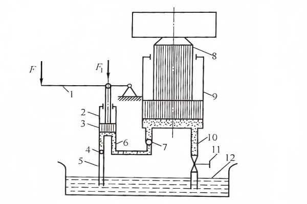
Figure 1-29: Hydraulic Jack Working Principle
- Lever handle
- Small cylinder
- Small piston
- Oil suction pipe
- Large piston
- Large cylinder
- Stop valve
- Oil tank
When force is applied to press down the handle, the small piston moves downward, the pressure in the lower cavity of the small piston increases, the check valve 4 closes, the check valve 7 opens, and the oil in the lower cavity is input into the lower cavity of the large cylinder 9 through the pipeline 6, forcing the large piston 8 to move upward and lift the heavy object. When the handle is lifted again to suck oil, the check valve 7 automatically closes to prevent oil from flowing back, thus ensuring that the heavy object does not fall by itself.
By continuously moving the handle back and forth, oil can be continuously pressed into the lower cavity of the large cylinder, gradually lifting the heavy object. If the stop valve 11 is opened, the oil in the lower cavity of the large cylinder flows back to the oil tank through the pipeline 10 and the stop valve 11, and the heavy object moves downward. This is the working principle of the hydraulic jack, which helps answer the question: what is hydraulics in its simplest form?
Key Principles from Hydraulic Jack Operation
1. Hydraulic transmission uses liquid (generally mineral oil) as the working medium for transmitting motion and power, and the transmission must go through two energy conversions. When the lever is pressed down, the small cylinder 2 outputs pressure oil, converting mechanical energy into pressure energy of the oil. The pressure oil pushes the large piston 8 to lift the heavy object, converting the pressure energy of the oil back into mechanical energy.
2. The oil must be transmitted in a closed container (or closed system) and there must be changes in the closed volume. If the container is not sealed, the necessary pressure cannot be formed. If the closed volume does not change, oil suction and pressure cannot be achieved, and it is impossible to use pressurized liquid to transmit motion and power.
Hydraulic transmission works by utilizing the pressure energy of liquids, which is fundamentally different from hydrodynamic transmission that works by utilizing the kinetic energy or potential energy of liquids in an unsealed state. This distinction is crucial to understanding what is hydraulics and how it differs from other fluid-based systems.
Hydraulic Transmission System in Simple Machine Tools
The hydraulic transmission system of a machine tool worktable is much more complex than that of a jack. As shown in Figure 1-30, it consists of an oil tank, filter, hydraulic pump, relief valve, on-off valve, throttle valve, directional valve, hydraulic cylinder, and oil pipes and joints connecting these components.
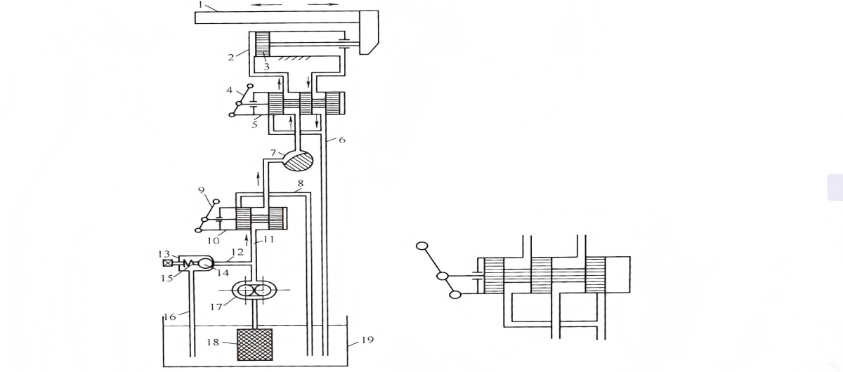
Figure 1-30: Hydraulic Transmission System of Machine Tool Worktable
What is hydraulics' application in machine tools? The working principle is as follows: After the hydraulic pump is driven by an electric motor, it draws oil from the oil tank. The oil enters the hydraulic pump through the filter. The oil in the pump cavity goes from low pressure at the inlet to high pressure at the pump outlet. In the state shown in Figure 1-30(a), it enters the left cavity of the hydraulic cylinder through the on-off valve, throttle valve, and directional valve, pushing the piston to move the worktable to the right. At this time, the oil in the right cavity of the hydraulic cylinder is discharged into the oil tank through the directional valve and oil return pipe 6.
If the directional valve handle is switched to the state shown in Figure 1-30(b), the oil in the pressure pipe will enter the right cavity of the hydraulic cylinder through the on-off valve, throttle valve, and directional valve, pushing the piston to move the worktable to the left, and the oil in the left cavity of the hydraulic cylinder will flow back to the oil tank through the directional valve and oil return pipe 6.
The moving speed of the worktable is adjusted through the throttle valve. When the throttle valve is opened larger, more oil enters the hydraulic cylinder, and the moving speed of the worktable increases. When the throttle valve is closed smaller, less oil enters the hydraulic cylinder, and the moving speed of the worktable decreases. This speed control mechanism is a key aspect of what is hydraulics in practical applications.
In order to overcome various resistances encountered when moving the worktable, the hydraulic cylinder must generate a sufficiently large thrust, which is generated by the oil pressure in the hydraulic cylinder. The greater the resistance to be overcome, the higher the oil pressure in the cylinder; otherwise, the pressure is lower. This phenomenon illustrates a basic principle of hydraulic transmission - pressure depends on load.
Composition of Hydraulic Transmission Systems
From the working process of the machine tool worktable hydraulic system, it can be seen that a complete hydraulic system that can work normally should consist of five main parts, which help define what is hydraulics as a complete technology.
| Component Part | Description |
|---|---|
| Energy Device (Power Element) | The energy device, also known as the power element, supplies pressure oil to the hydraulic system and converts mechanical energy into hydraulic energy. The most common device is the hydraulic pump. |
| Actuating Device (Element) | The actuating device converts hydraulic energy into mechanical energy to drive the working mechanism. These devices include hydraulic cylinders that perform linear motion and hydraulic motors that perform rotational motion, which are also called the actuating elements of the hydraulic system. |
| Control and Regulation Devices (Elements) | These are devices that control or regulate the pressure, flow rate, or flow direction in the system, such as relief valves, throttle valves, directional valves, on-off valves, etc. |
| Auxiliary Devices (Elements) | Other devices besides the above three parts, such as oil tanks, filters, oil pipes, etc. They are essential devices to ensure the normal operation of the system. |
| Working Medium | The fluid that transmits energy, such as hydraulic oil. |
Key Components Functions
Energy Conversion in Hydraulics
Characteristics of Hydraulic Transmission
Understanding what is hydraulics also involves knowing its key characteristics. The characteristics of hydraulic transmission define its advantages and applications in various industries. These characteristics stem from the fundamental principles of fluid dynamics applied in a controlled environment.
1. Working Pressure of Power Elements Depends Mainly on Load
In the system shown in Figure 1-29, if the flow resistance in the pipeline is ignored, it can be considered that the force transmission conforms to the principle of hydrostatics, that is, the pressure acting on the pistons of the small cylinder 2 and large cylinder 9 is equal (P).
Then we have:
F₁/A₁ = F₂/A₂ = p
Where A₁ and A₂ are the piston areas of the small cylinder 2 and large cylinder 9; F₁ and F₂ are the forces acting on the pistons of the small cylinder 2 and large cylinder 9.
When the structural size elements A₁ and A₂ are fixed, the oil pressure in the hydraulic cylinder depends on the force F₂ required to lift the load. The force F₁ on the manual pump depends on the oil pressure in the hydraulic cylinder. Therefore, the heavier the load to be lifted, the higher the oil pressure and the greater the required force F₁. Conversely, if working with no load and ignoring friction, both the oil pressure and the force F₁ required for the manual pump operation are zero.
This basic characteristic of hydraulic transmission can be briefly expressed as "pressure depends on load," which is fundamental to understanding what is hydraulics in practical operation.
2. Movement Speed of Actuating Elements Depends Mainly on Input Flow Rate and Is Independent of Load
In the system shown in Figure 1-29, if the compressibility of the liquid and other factors are not considered, it can be considered that the transmission of its movement speed conforms to the equation of continuity of fluid flow, that is, the principle that the volume changes of the closed working chamber are equal. The volume changed by the downward movement of the piston of the small cylinder 2 should be equal to the volume changed by the upward movement of the piston of the large cylinder 9.
Then we have:
A₁h₁ = A₂h₂ = V
Where h₁ and h₂ are the displacements of the pistons of the small cylinder 2 and large cylinder 9.
Dividing both sides of the above equation by the movement time t of the piston, we get:
A₁v₁ = A₂v₂ = q
Where v₁ and v₂ are the average movement speeds of the pistons of the small cylinder 2 and large cylinder 9; q is the average flow rate output by the hydraulic pump.
When the structural size elements A₁ and A₂ are fixed, the moving speed v₂ of the large cylinder 9 only depends on the input flow rate q. The larger the flow rate q input to the hydraulic cylinder, the greater the movement speed v₂. This basic characteristic of hydraulic transmission can be briefly expressed as "speed depends on flow," which is another key concept when exploring what is hydraulics.
3. Working Pressure and Flow Rate Are Independent of Each Other
The flow rate of a positive displacement hydraulic pump depends on the size of the working cavity of the hydraulic pump and is basically independent of the working pressure of the hydraulic pump. Regardless of how the load of the hydraulic jack changes, as long as the supplied flow rate is constant, the moving speed of the heavy object rising is constant.
Similarly, regardless of how fast the piston of the hydraulic cylinder moves, as long as the load is constant, the liquid pressure required to push the load is determined. That is, the above two characteristics exist independently and do not affect each other. Therefore, in theory, a positive displacement hydraulic pump can output a basically constant flow rate at any high pressure, ensuring that the actuating elements can work stably. This is the reason why positive displacement hydraulic pumps are used in hydraulic systems, and understanding this helps answer what is hydraulics' advantage in power transmission.
4. Power of Hydraulic System Equals the Product of Flow Rate and Pressure
In the system shown in Figure 1-29, if losses are ignored, the input power P₁ of the system is:
P₁ = F₁v₁ = pA₁v₁ = pq
The output power P₂ is:
P₂ = F₂v₂ = pA₂v₂ = pq
It can be seen that the fluid parameter corresponding to the external load is pressure, and the fluid parameter corresponding to the movement speed is flow rate. Pressure and flow rate are two basic parameters in hydraulic systems, and their relationship defines what is hydraulics' power transmission capability.
Summary of Hydraulic Transmission Characteristics
Pressure in the system is determined by the load, not the pump
Speed of actuators is determined by flow rate, not pressure
Pressure and flow rate are independent parameters
System power equals the product of pressure and flow rate
Requires a closed system with changing volume chambers
Involves two energy conversions (mechanical to hydraulic and back)
Conclusion
Hydraulic transmission systems play a crucial role in modern machinery, offering efficient power transmission with unique characteristics that make them suitable for various applications. From simple hydraulic jacks to complex machine tool systems, the principles remain consistent: using fluid pressure to transmit power with pressure dependent on load and speed dependent on flow rate.
What is hydraulics' significance in modern engineering? It's a versatile technology that enables precise control of large forces, making it indispensable in industries ranging from manufacturing to construction. By understanding these fundamental principles and characteristics, engineers can design and utilize hydraulic systems more effectively for diverse applications.