Overview of Hydraulic Valves
Hydraulic systems rely on hydraulic valves to control the flow, pressure, and direction of hydraulic fluid within a circuit. These essential components regulate the operation of hydraulic machinery, ensuring precise movement and force application in various industrial settings.
The functionality of hydraulic valves is based on fundamental fluid dynamics principles, where the controlled redirection of pressurized fluid generates mechanical force and motion. From simple on/off operations to complex proportional control, hydraulic valves are critical in translating hydraulic energy into useful work.
Modern hydraulic valves come in various configurations, each designed for specific applications and performance requirements. They can be manually, mechanically, hydraulically, or electrically actuated, providing flexibility in system design and operation.
The selection of appropriate hydraulic valves depends on factors such as flow rate, pressure rating, response time, environmental conditions, and the specific control needs of the hydraulic system. Proper valve selection ensures efficiency, reliability, and safety in hydraulic operations.
Industries that heavily utilize hydraulic valves include manufacturing, construction, agriculture, aerospace, mining, and marine. In each of these sectors, hydraulic valves contribute to the precise operation of equipment ranging from simple hydraulic presses to complex robotic systems.
A comprehensive hydraulic system featuring various types of hydraulic valves working in conjunction
Key Characteristics of Quality Hydraulic Valves
Precise Control
Accurate flow and pressure regulation for consistent system performance
Pressure Resistance
Ability to withstand system pressures without leakage or failure
Quick Response
Rapid actuation and reaction to control signals for dynamic operations
Cross-section of a spool-type directional control valve showing flow paths
Directional control valves are fundamental components in hydraulic systems that manage the path of fluid flow. These valves determine which path the hydraulic fluid takes, enabling the control of actuator direction, start, and stop functions in hydraulic systems utilizing hydraulic valves.
The primary function of directional control valves is to regulate the direction of fluid flow through a hydraulic circuit. They achieve this by opening or closing passages within the valve body, effectively directing flow to different components such as cylinders or motors. This functionality makes them indispensable among various hydraulic valves.
These hydraulic valves are classified by several characteristics, including the number of ports, spool positions, actuation method, and flow capacity. Common configurations include 2-way, 3-way, and 4-way valves, with spool positions ranging from 2-position to multi-position designs.
Directional control valves can be actuated manually, mechanically, hydraulically, pneumatically, or electrically. Solenoid-actuated directional valves are particularly popular in automated systems, offering fast response times and easy integration with electronic control systems.
Applications for these hydraulic valves include controlling the extension and retraction of hydraulic cylinders, reversing the rotation of hydraulic motors, and directing flow to different branches of a hydraulic circuit. Proper selection ensures efficient operation and longevity of the entire hydraulic system.
Common Types of Directional Control Valves
| Valve Type | Configuration | Typical Applications |
|---|---|---|
| Check Valves | 2-way, 2-position | Preventing backflow in hydraulic circuits |
| Spoold Valves | 3-way or 4-way, 2 or 3-position | Controlling cylinder movement, motor direction |
| Poppet Valves | Various configurations | High-pressure systems, quick disconnects |
| Rotary Valves | Multiple ports, rotating spool | Direction control in mobile equipment |
Pressure control valves are essential hydraulic valves designed to regulate and maintain the pressure levels within hydraulic systems. These critical components prevent system overpressure, control actuation forces, and manage pressure levels in different parts of a hydraulic circuit.
The operation of pressure control valves is based on balancing hydraulic force against a opposing force, typically provided by a spring. When system pressure reaches a predetermined level, it overcomes the spring force, causing the valve to open and relieve pressure either by diverting flow, reducing flow, or venting excess fluid back to the reservoir.
These hydraulic valves are available in various configurations to suit different pressure control requirements. Relief valves, for example, protect the system from overpressure by opening at a preset pressure level, while pressure reducing valves maintain a lower, constant pressure in a specific branch of the system regardless of fluctuations in the main circuit.
Sequence valves are another type of pressure control valve that enable one hydraulic function to be completed before another begins, using pressure to actuate the valve. Counterbalance valves prevent hydraulic cylinders from moving under load due to gravity, maintaining controlled movement.
Properly selected and adjusted pressure control hydraulic valves are crucial for system safety, efficiency, and performance. They protect components from damage due to excessive pressure, ensure consistent operation, and allow for energy-efficient system design by limiting pressure to only what is necessary for each function.
Pressure control valve assembly with integrated pressure gauge for system monitoring
Pressure Control Valve Performance Characteristics
Precision flow control valve with visual flow indicator for accurate adjustment
Flow control valves are specialized hydraulic valves designed to regulate the rate of fluid flow within hydraulic systems. By controlling flow rate, these valves directly influence the speed of hydraulic actuators such as cylinders and motors, making them essential for precise motion control.
The basic principle behind flow control valves involves creating a constriction in the fluid path, which limits the flow rate. The amount of restriction can be fixed or variable, allowing for either constant or adjustable flow rates. Some advanced designs also compensate for pressure variations to maintain consistent flow rates regardless of system pressure changes.
These hydraulic valves come in several types, including needle valves, which provide fine flow adjustment through a tapered needle and seat arrangement; globe valves, which offer good throttling capabilities; and proportional flow control valves, which allow for remote flow adjustment through electrical signals.
Pressure-compensated flow control valves are particularly valuable in applications where consistent actuator speed is required despite varying loads. These valves automatically adjust the flow area to maintain a constant flow rate, even as system pressure changes due to varying load conditions.
The proper application of flow control hydraulic valves ensures precise control of machine movements, synchronized operation of multiple actuators, and efficient use of hydraulic power. They are widely used in manufacturing machinery, material handling equipment, and any application requiring controlled speed and motion.
Flow Control Valve Selection Criteria
- Desired flow rate range and adjustment precision requirements
- System pressure rating and potential pressure fluctuations
- Fluid compatibility with valve materials
- Temperature range of the operating environment
- Required response time for flow adjustments
- Need for pressure compensation or flow division
- Actuation method (manual, hydraulic, electric)
- Installation space constraints and port configuration
Electro-hydraulic servo valves represent the pinnacle of precision control among hydraulic valves, offering exceptional accuracy in regulating fluid flow and pressure in response to electrical input signals. These sophisticated devices bridge electronic control systems with hydraulic power, enabling highly precise positioning, speed control, and force regulation.
The operation of electro-hydraulic servo valves involves converting a small electrical signal (typically from a controller) into a proportional hydraulic flow or pressure output. This conversion is achieved through a torque motor or voice coil that positions a spool or flapper within the valve, which in turn modulates the hydraulic flow.
What distinguishes these hydraulic valves from other types is their closed-loop feedback mechanism, which continuously compares the actual valve position with the desired position specified by the input signal. This feedback allows for immediate corrections, resulting in exceptional accuracy, repeatability, and dynamic response.
Electro-hydraulic servo valves are characterized by their high response speed, precise control resolution, and ability to handle varying loads while maintaining control accuracy. They typically offer flow rates proportional to the input current, with excellent linearity and minimal hysteresis.
These advanced hydraulic valves find applications in demanding environments where precision is paramount, such as flight simulators, industrial robots, precision machine tools, and aerospace systems. Their ability to provide precise control over large forces and movements makes them indispensable in modern automated manufacturing and testing equipment.
High-precision electro-hydraulic servo valve with integrated position feedback sensor
Key Advantages of Electro-Hydraulic Servo Valves
Exceptional Precision
Sub-micron level positioning capability for ultra-precise control applications
Rapid Response
Microsecond-level response times for dynamic and high-speed applications
Linear Performance
Excellent linearity between input signal and output flow/pressure
Dynamic Control
Superior performance under varying load conditions and dynamic operations
Electro-hydraulic proportional valve with integrated amplifier and control interface
Electro-hydraulic proportional valves represent a versatile category of hydraulic valves that provide proportional control of flow or pressure in response to an electrical input signal. These valves offer a balance between precision and cost-effectiveness, making them widely used in industrial applications requiring controlled motion and force.
Unlike simple on/off hydraulic valves, proportional valves modulate their output continuously in relation to the input signal. This means that a 50% input signal will typically result in approximately 50% of the maximum flow or pressure output, allowing for smooth, variable control of hydraulic actuators.
These hydraulic valves incorporate a proportional solenoid or torque motor that positions a spool or poppet within the valve body. The position of this moving element determines the size of the flow passage, thereby controlling the flow rate or pressure. Many modern designs include feedback mechanisms to improve accuracy and reduce hysteresis.
Electro-hydraulic proportional valves are available in various configurations, including directional control, pressure control, and flow control types. They can be designed as standalone valves or integrated into complex valve manifolds, providing flexibility in system design.
Applications for these hydraulic valves include material handling equipment, injection molding machines, presses, and automated production lines. They offer an ideal solution when precise control is needed but the extreme accuracy of servo valves is unnecessary, providing a cost-effective balance between performance and complexity.
Comparison: Proportional Valves vs. Servo Valves
| Characteristic | Electro-Hydraulic Proportional Valves | Electro-Hydraulic Servo Valves |
|---|---|---|
| Accuracy | Good (typically ±1-3%) | Excellent (typically ±0.1-0.5%) |
| Response Time | Moderate (10-100 ms) | Fast (1-10 ms) |
| Cost | Lower | Higher |
| Complexity | Moderate | High |
| Maintenance | Simpler | More demanding |
| Typical Applications | Industrial machinery, material handling | Precision systems, aerospace, testing |
Cartridge valves, also known as insert valves, are compact, modular hydraulic valves designed to be inserted into valve manifolds or directly into machine components. This innovative design offers significant advantages in terms of space savings, system integration, and customization flexibility compared to traditional hydraulic valve configurations.
The basic design of a cartridge valve consists of a cylindrical cartridge that contains all the functional components of the valve, including the closing element (poppet, spool, or ball), spring, and seals. This cartridge is inserted into a machined cavity in a manifold block or component body, where it controls fluid flow through internal passages.
These hydraulic valves are available in a wide range of configurations, including check valves, pressure relief valves, directional control valves, flow control valves, and proportional valves. This variety allows system designers to create custom hydraulic circuits by combining different cartridge valves in a single manifold block.
One of the primary advantages of cartridge valves is their compact size, which allows for high-density integration of hydraulic functions. This results in more efficient use of space, reduced overall system size, and simplified installation. Additionally, the modular design simplifies maintenance, as individual cartridges can be replaced without disassembling the entire manifold.
Cartridge hydraulic valves are widely used in mobile hydraulic systems, industrial machinery, and custom hydraulic manifolds. They are particularly valued in applications where space is limited, system complexity is high, or custom hydraulic solutions are required. Their robust design also makes them suitable for high-pressure applications up to several thousand psi.
Assortment of cartridge valves and a manifold block showing installation cavities
Types of Cartridge Valves and Their Functions
Pressure Control Cartridges
- Relief valves - protect against overpressure
- Reducing valves - maintain lower pressure in branches
- Sequence valves - control operation order
- Counterbalance valves - prevent free fall
Directional Control Cartridges
- Check valves - allow one-way flow
- Pilot-operated check valves - controlled one-way flow
- Solenoid-operated directional cartridges
- Ball valves - on/off flow control
Flow Control Cartridges
- Fixed orifice cartridges - constant flow restriction
- Adjustable flow control cartridges
- Pressure-compensated flow controls
- Proportional flow control cartridges
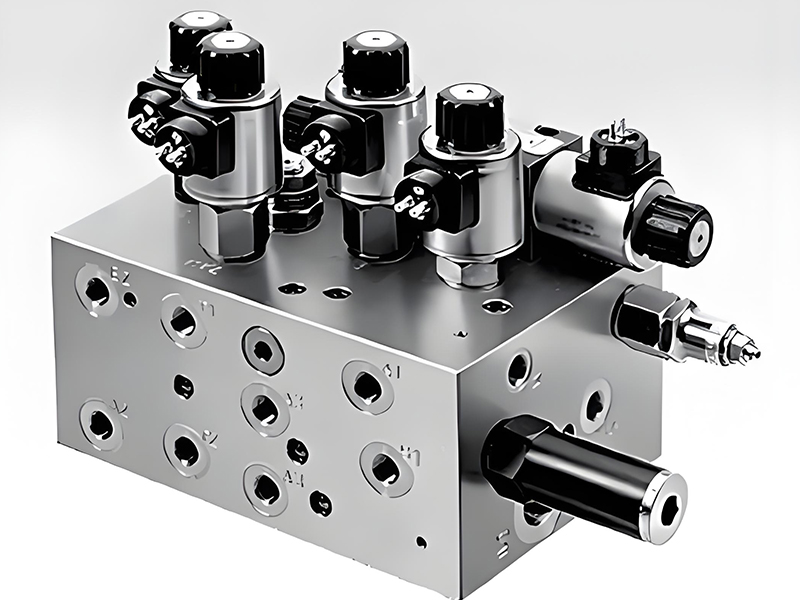
Hydraulic manifold valve assembly showing integrated valve stations and fluid connections
Manifold valves, also known as stack valves or modular valves, are integrated assemblies of hydraulic valves designed to mount in a stacked configuration or as part of a custom manifold block. This design approach simplifies hydraulic system design, reduces installation space, and minimizes potential leak points compared to systems using individual valves connected with hoses or tubing.
The concept behind manifold valves involves mounting multiple valve sections onto a common base or stacking them together, with internal passages connecting the valves instead of external piping. This creates a compact, integrated hydraulic control center where fluid is directed through internal channels between the various hydraulic valves in the manifold.
These integrated valve assemblies typically include a combination of directional control valves, pressure control valves, and flow control valves, all mounted on a common manifold. The manifold itself contains the necessary internal passages to connect the valves in the desired hydraulic circuit configuration.
Manifold valves offer several advantages, including reduced system complexity, smaller footprint, fewer potential leak points, and simplified installation and maintenance. They also provide improved response times due to shorter fluid paths and reduced volume between components.
In addition to standard manifold configurations, custom manifold blocks can be designed to integrate specific hydraulic valves into a single, compact component tailored to a particular application. This custom approach is particularly valuable in mobile hydraulic systems, where space is at a premium, and in industrial machinery requiring complex hydraulic control in a limited space.
Applications and Benefits of Manifold Valves
Common Applications
Mobile Hydraulics
Construction equipment, agricultural machinery, and material handling vehicles
Industrial Machinery
Machine tools, presses, injection molding machines, and automated production lines
Marine Applications
Shipboard systems, offshore equipment, and marine hydraulic controls
Aerospace Systems
Ground support equipment, flight simulators, and aerospace test systems
Key Benefits
Space Savings
Compact design reduces the overall footprint of hydraulic systems
Reduced Leak Points
Internal passages eliminate many potential leakage points
Improved Performance
Shorter flow paths reduce pressure drops and improve response times
Simplified Installation
Integrated design reduces assembly time and complexity
Enhanced Reliability
Reduced number of connections improves system reliability
Comprehensive Solutions with Hydraulic Valves
From simple directional control to precise servo applications, hydraulic valves form the backbone of modern hydraulic systems. The diverse range of valve types ensures that there is an optimal solution for every hydraulic application, combining efficiency, precision, and reliability.