Orifice Flow and Gap Flow in Hydraulic Systems
A comprehensive analysis of flow characteristics, mathematical models, and practical applications in hydraulic engineering, including essential principles for optimizing a hydraulic flow meter.
Hydraulic systems rely on the controlled movement of fluids through various components to transmit power and motion. Understanding the behavior of fluid flow through orifices and gaps is fundamental to designing efficient hydraulic systems, including accurate measurement devices like a hydraulic flow meter. This technical resource explores the fundamental principles, mathematical formulations, and practical considerations of orifice discharge and gap flow in hydraulic components.
The precise calculation of flow rates through orifices and gaps is critical for system performance, energy efficiency, and component longevity. Engineers must account for these flow characteristics when designing valves, cylinders, pumps, and measurement instruments such as a hydraulic flow meter. This knowledge enables the optimization of system parameters to achieve desired performance while minimizing energy losses and leakage.
I. Orifice Flow
1. Thin-Walled Orifice Flow
Figure 1: Thin-walled orifice flow demonstrating vena contracta formation, a critical consideration for hydraulic flow meter calibration
Definition
A thin-walled orifice is defined as an opening where the orifice edge thickness \( \delta \) and diameter \( d \) satisfy the relationship \( \delta/d \leq 0.5 \), with sharp, right-angled edges. This configuration is often referenced in hydraulic flow meter specifications due to its predictable flow characteristics.
Flow Characteristics
When fluid flows through a thin-walled orifice, the streamlines cannot abruptly change direction, causing the fluid jet to contract to a minimum cross-section known as the vena contracta (section \( c-c \)) downstream of the orifice. This contraction is a key factor in determining the accuracy of a hydraulic flow meter. Beyond the vena contracta, the jet expands again, creating a region of turbulence and eddies. The flow at the vena contracta is considered to be缓变流 (gradually varied flow), simplifying analysis.
Bernoulli's Equation
Applying Bernoulli's equation between the upstream section and the vena contracta (section \( c-c \)) allows us to derive the velocity and flow rate equations, which are essential for both system design and hydraulic flow meter calibration:
Where:
- \( p_1, p_2 \) = pressures at upstream and vena contracta sections
- \( v_1, v_2 \) = velocities at upstream and vena contracta sections
- \( \rho \) = fluid density
- \( g \) = acceleration due to gravity
- \( \xi \) = loss coefficient
In practical applications, especially when sizing a hydraulic flow meter, the upstream velocity head \( v_1^2/(2g) \) is often negligible because the pipe cross-sectional area is much larger than the orifice area. This simplifies the equation to:
Where \( \boldsymbol{\varphi = 1/\sqrt{1+\xi}} \) is the velocity coefficient, a critical parameter in hydraulic flow meter accuracy.
Flow Rate Formula
To determine the volumetric flow rate, we must consider the contraction of the fluid jet. Let \( A_c \) be the area of the vena contracta and \( A \) be the orifice area. The contraction coefficient is defined as \( \boldsymbol{\varepsilon = A_c/A} \). The flow rate equation, fundamental to hydraulic flow meter operation, becomes:
Where \( \boldsymbol{C_d = \varepsilon \varphi} \) is the discharge coefficient, a key calibration parameter for any precision hydraulic flow meter.
Experimental Values
For fully contracted orifices (where \( D/d \geq 7 \), with \( D \) being the pipe diameter), experimental data has established typical values that are critical for hydraulic flow meter design:
| Parameter | Typical Range | Significance for Hydraulic Flow Meter |
|---|---|---|
| Contraction coefficient (\( \varepsilon \)) | 0.63~0.64 | Affects effective flow area measurement |
| Loss coefficient (\( \xi \)) | 0.05~0.06 | Influences pressure drop calculations |
| Velocity coefficient (\( \varphi \)) | 0.97~0.98 | Determines actual velocity from theoretical values |
| Discharge coefficient (\( C_d \)) | 0.60~0.62 | Primary calibration factor for hydraulic flow meter |
These values are essential when calibrating a hydraulic flow meter, as they account for the difference between theoretical and actual flow behavior. Manufacturers often provide specific discharge coefficients for their orifice-based hydraulic flow meter products based on extensive testing.
2. Short Tube Orifice Flow
Figure 2: Comparison of flow patterns in thin-walled orifice vs. short tube orifice, showing different pressure recovery characteristics important for hydraulic flow meter design
Definition
A short tube orifice is characterized by a wall thickness \( l = (2\sim4)d \), where \( d \) is the orifice diameter. For longer tubes, flow characteristics are calculated using pipe flow formulas rather than orifice equations. Short tube orifices are sometimes used in specialized hydraulic flow meter designs where pressure recovery is important.
Bernoulli's Equation
Applying Bernoulli's equation between the upstream section (1-1) and the exit section (2-2), and neglecting the upstream velocity \( v_1 \) as in the thin-walled case, we get:
Velocity and Flow Rate
The velocity and flow rate equations for short tube orifices, which are used in certain hydraulic flow meter configurations, are:
For short tube orifices, the discharge coefficient \( C_d = \varphi \) because the vena contracta that forms inside the tube reattaches to the tube walls before exit, eliminating the contraction effect seen in thin-walled orifices. Experimental data shows that \( \varphi = 0.8\sim0.82 \) for short tube orifices, with higher flow resistance than thin-walled orifices. This difference is important when selecting the appropriate hydraulic flow meter for a specific application.
Engineering Insight
When selecting between thin-walled and short tube orifices for flow measurement, a hydraulic flow meter using a short tube design may offer advantages in certain applications due to its more stable flow pattern and better pressure recovery, despite its lower discharge coefficient. This makes it suitable for systems where energy loss is a primary concern.
II. Gap Flow
Flow through gaps is a critical consideration in hydraulic components such as pistons and cylinders, spools and valve bodies, and between other mating surfaces. These flows are typically laminar due to the small gap dimensions. Understanding gap flow is essential for minimizing leakage, optimizing efficiency, and ensuring proper operation of components, including the housing and connections of a hydraulic flow meter.
1. Parallel Gaps with Fixed Walls
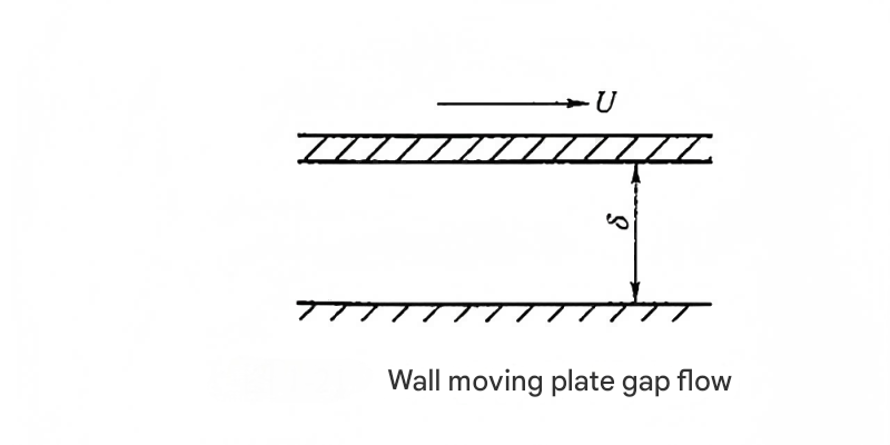
Figure 3: Velocity profile in a parallel fixed wall gap, illustrating the parabolic distribution used in hydraulic flow meter gap analysis
Infinite Width Gaps
For an infinitely wide gap, the flow rate per unit width can be derived from Newton's law of viscosity. This fundamental relationship is important for analyzing leakage around hydraulic flow meter components:
Where:
- \( \delta \) = gap height
- \( l \) = gap length
- \( \mu \) = dynamic viscosity of the fluid
- \( \Delta p \) = pressure difference across the gap
Finite Width Gaps
For finite width gaps (with width \( b \) and moderate length \( l \)), a correction factor \( c \) is introduced to account for end effects. This factor, which relates to the ratio \( l/(\delta Re) \), is particularly important in compact hydraulic components like a hydraulic flow meter. The flow rate equation becomes:
Where \( Re \) is the Reynolds number. When \( l/(\delta Re) \) is sufficiently large, the correction factor \( c \to 1 \), and the finite width solution approaches the infinite width case. This relationship is critical for accurately predicting leakage in precision components such as the moving parts of a hydraulic flow meter.
2. Parallel Plate Gaps with Moving Walls
When one of the plates forming the gap moves with a velocity \( U \), the flow rate becomes the combination of pressure-driven flow and shear-driven flow. This is particularly relevant in hydraulic components with moving parts, such as pistons, and can affect the performance of a hydraulic flow meter installed in such systems.
The total flow rate is expressed as:
The sign convention is as follows: the "+" sign is used when the plate velocity \( U \) is in the same direction as the pressure-driven flow, and the "-" sign when they are in opposite directions. This relationship is crucial for analyzing leakage in dynamic seals and piston-cylinder interfaces, which can affect the accuracy of a hydraulic flow meter measuring system flow rates.
Figure 5: Comparison of flow rates in fixed vs. moving wall gaps, showing the significant impact of wall motion on leakage, a factor in hydraulic flow meter accuracy
3. Annular Gap Flow
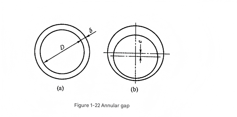
Figure 6: Concentric and eccentric annular gap configurations, showing how eccentricity increases leakage, a critical consideration for hydraulic flow meter installation
Concentric Annular Gaps
For concentric annular gaps (as shown in Figure 1-22(a)), the flow equations are derived by substituting the circumference \( \pi D \) (where \( D \) is the diameter of the annulus) for the width \( b \) in the parallel plate equations. This geometry is common in hydraulic cylinders and can affect the accuracy of a hydraulic flow meter measuring system flow when significant leakage occurs.
For fixed walls (\( U=0 \)):
For moving walls with velocity \( U \):
Eccentric Annular Gaps
Eccentricity significantly affects flow through annular gaps. For eccentric annular gaps (as shown in Figure 1-22(b)), an eccentricity factor \( \boldsymbol{\varepsilon = e/\delta} \) is introduced, where \( e \) is the eccentricity (distance between centers). This is particularly important in worn components, which can increase leakage and affect the performance of a hydraulic flow meter.
The flow rate equation for eccentric annular gaps is:
When \( \varepsilon=1 \) (maximum eccentricity), the flow rate increases significantly:
This represents a 250% increase compared to concentric flow, highlighting the importance of maintaining concentricity in hydraulic components to minimize leakage. This is particularly relevant when installing a hydraulic flow meter, as excessive leakage can lead to inaccurate measurements.
4. Radial Flow in Parallel Plates
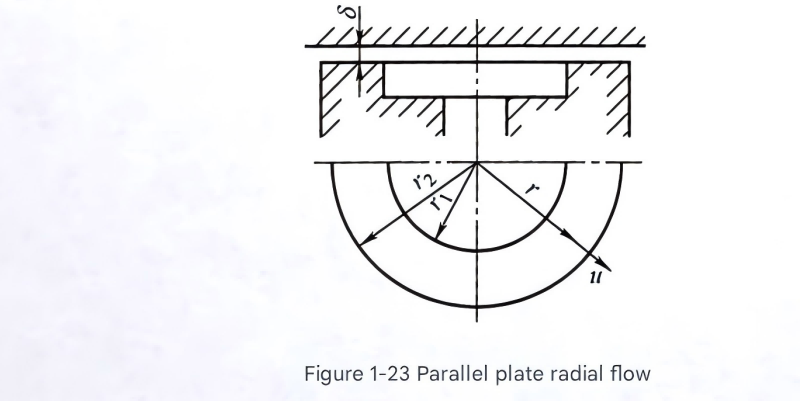
Figure 7: Radial flow between parallel plates, illustrating the expanding flow pattern found in certain hydraulic components and specialized hydraulic flow meter designs
Radial flow occurs between parallel plates where fluid flows outward (or inward) from a central source. This configuration is found in hydraulic components such as pressure relief valves, bearings, and some specialized hydraulic flow meter designs. For radial gaps with inner radius \( r_1 \) and outer radius \( r_2 \), the flow rate is given by:
Where \( C_e \) is a correction factor related to \( r_1/(\delta Re) \), as shown in Figure 1-24. This correction factor accounts for the transition from laminar to more complex flow patterns in radial geometries, which is important for accurate hydraulic flow meter readings in such configurations.
Practical Consideration
In hydraulic system design, radial gap flows often represent significant leakage paths that can reduce efficiency and affect measurement accuracy. A properly calibrated hydraulic flow meter can help identify excessive leakage by comparing measured flow rates with theoretical system requirements, enabling maintenance or redesign before performance degradation becomes severe.
Practical Applications and Summary
The principles of orifice and gap flow are fundamental to hydraulic system design and analysis. These flows affect component performance, system efficiency, and measurement accuracy. A well-designed hydraulic flow meter relies on a thorough understanding of these flow characteristics to provide accurate measurements across a range of operating conditions.
From a practical standpoint, engineers use these flow equations to:
- Design efficient valves and flow control devices, incorporating accurate hydraulic flow meter feedback
- Minimize leakage in hydraulic cylinders and actuators, verified through hydraulic flow meter measurements
- Calculate pressure drops across components to ensure proper system operation
- Optimize the performance of hydraulic pumps and motors
- Calibrate and select appropriate hydraulic flow meter technologies for specific applications
- Predict and prevent cavitation in critical system components
Whether analyzing the flow through a thin-walled orifice in a hydraulic flow meter or calculating leakage through the annular gap in a piston-cylinder assembly, these fundamental principles provide the foundation for hydraulic system design and optimization. By applying these equations and understanding their limitations, engineers can develop more efficient, reliable, and cost-effective hydraulic systems.