Fluid Dynamics
Fluid dynamics is the science that studies the laws governing the motion of fluids under external forces, examining the relationships between hydrodynamic and kinematic physical quantities. Specifically, it investigates the relationship between the forces acting on a fluid and the velocity of its motion. The primary physical laws applied include Newton's second law and the law of conservation of mechanical energy. Understanding these principles helps answer the fundamental question: how do hydraulics work?

Fluid flow visualization demonstrating velocity gradients and pressure distributions
Basic Concepts of Fluid Motion
To understand how do hydraulics work, we must first grasp the fundamental concepts that describe fluid behavior. These concepts form the foundation for analyzing and predicting fluid motion in various engineering applications.
Table 1-16: Basic Concepts of Fluid Motion
| Concept | Description |
|---|---|
| Ideal Fluid | An ideal fluid is one that has no viscosity. While no real fluid is completely without viscosity, this theoretical concept simplifies many fluid dynamics analyses, helping us better understand how do hydraulics work in practical applications. |
| Steady and Unsteady Flow | In a flow field, steady flow occurs when the fluid's motion parameters (pressure, velocity, density, etc.) at any point do not change with time. Unsteady flow occurs when one or more of these parameters change over time. This distinction is crucial in determining how do hydraulics work under different operational conditions. |
| Pathlines and Streamlines |
A pathline is the trajectory of a fluid particle over a period of time. A streamline is a curve in the flow field at a specific instant where the velocity direction of fluid particles at each point on the curve is tangent to the curve at that point. Properties of streamlines and pathlines: - A streamline exists at a specific instant, while a pathline forms over a period of time. - Each point on a streamline contains a fluid particle, so every streamline contains countless fluid particles, whereas a pathline represents the trajectory of a single fluid particle. - In unsteady flow, velocity changes with time, resulting in different streamline shapes at different instants, so streamlines and pathlines do not coincide. - In steady flow, velocity does not change with time, so streamline shapes remain constant, and streamlines completely coincide with pathlines. - Streamlines cannot intersect (except at singular points). Understanding these properties is essential to answering how do hydraulics work in various flow scenarios. |
| Stream Tubes, Stream Filaments, and Total Flow |
① Stream Tube: A tubular surface formed by drawing streamlines through each point of a closed curve in the flow field. Since there is no velocity component normal to the stream tube, fluid cannot pass through the stream tube surface, so the stream tube acts similarly to a pipe. ② Stream Filament: The entire fluid contained within a stream tube is called a stream filament. A stream filament with an infinitely small cross-section is called a micro stream filament. The motion parameters at all points on the cross-section of a micro stream filament are the same. As the cross-sectional area approaches zero, the micro stream filament approaches a streamline as its limit, so streamlines can sometimes be used to represent micro stream filaments. ③ Total Flow: The sum of all micro stream filaments within the flow boundary is called total flow. This concept helps engineers model complex flow systems when analyzing how do hydraulics work in practical applications. |
| Effective Cross-section, Wetted Perimeter, and Hydraulic Radius |
① Effective Cross-section: A cross-section perpendicular to the velocity at each point on the section is called the effective cross-section, denoted by A. ② Wetted Perimeter: The perimeter of contact between the fluid and the solid boundary on the effective cross-section is called the wetted perimeter, denoted by χ, as shown in Figure 1-12. ③ Hydraulic Radius: The ratio of the effective cross-section to the wetted perimeter is called the hydraulic radius, denoted by R. These geometric parameters are critical in calculating pressure drops and flow rates in pipe systems, directly impacting our understanding of how do hydraulics work in practical engineering designs. |
Streamlines in Steady Flow
In steady flow, streamlines remain constant over time and coincide with pathlines. This stability simplifies engineering calculations when determining how do hydraulics work in systems operating under constant conditions.
Pathlines in Unsteady Flow
In unsteady flow, pathlines of individual particles diverge from streamlines that change with time. This dynamic behavior creates challenges in predicting how do hydraulics work in systems with varying flow conditions.
Stream Tubes and Flow Characteristics
Figure 1-12: Stream tube visualization showing flow confinement within boundary streamlines
Stream tubes act as virtual conduits that guide fluid flow, preventing cross-flow between adjacent regions. This property is fundamental to understanding how do hydraulics work in piping systems and channel flows.
The behavior of fluid within stream tubes follows conservation laws that allow engineers to predict pressure changes, velocity variations, and flow rates. By analyzing these properties, we can design efficient hydraulic systems and answer the essential question of how do hydraulics work in various applications.
Continuity Equation
The continuity equation represents the law of conservation of mass in fluid mechanics. This fundamental principle is essential to understanding how do hydraulics work, as it describes how mass is conserved as fluid moves through a system.
Consider two arbitrary effective cross-sections A₁ and A₂ in a pipeline, with average velocities v₁ and v₂ respectively, and fluid densities ρ₁ and ρ₂. The mass of fluid flowing into the space between these two cross-sections per unit time is ρ₁A₁v₁, while the mass flowing out during the same time is ρ₂A₂v₂.
For steady flow, the mass entering and exiting the control volume between sections A₁ and A₂ must be equal:
ρ₁A₁v₁ = ρ₂A₂v₂ = constant
For incompressible fluids, the equation simplifies to:
A₁v₁ = A₂v₂ = constant
The product of velocity and cross-sectional area equals the flow rate:
Q = Av
Therefore, the equation A₁v₁ = A₂v₂ = constant can be written as:
Q₁ = Q₂ = constant
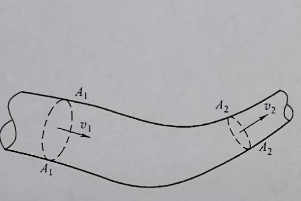
Figure 1-13: Schematic illustration for the continuity equation
Practical Implications
The continuity equation explains why fluid velocity increases in narrower sections of a pipe and decreases in wider sections. This principle is crucial to understanding how do hydraulics work in systems like water distribution networks, hydraulic machinery, and fluid transport systems. When the cross-sectional area decreases, velocity must increase to maintain constant flow rate, and vice versa.
Applications of the Continuity Equation
The continuity equation finds widespread application in engineering design and analysis, helping professionals answer how do hydraulics work in various scenarios:
- Pipeline design, where diameter changes must be calculated to maintain desired flow rates
- Venturi meters and flow nozzles used to measure fluid flow rates
- Hydraulic systems where force multiplication is achieved through area and velocity relationships
- Aerodynamics, explaining how airspeed changes over wing surfaces generate lift
- Channel design for open water flow in irrigation systems and river engineering
By applying the continuity equation, engineers can predict how fluid behavior changes in different parts of a system, forming a foundational knowledge base for understanding how do hydraulics work in practical applications.
Bernoulli's Equation and Its Applications
Bernoulli's equation represents the law of conservation of energy in fluid mechanics, describing the relationship between pressure, velocity, and elevation in a flowing fluid. This equation is perhaps the most important tool in answering how do hydraulics work in countless engineering applications.
① Ideal Fluid Bernoulli Equation
Bernoulli's equation reflects the law of energy transformation during fluid motion. As shown in Figure 1-14, consider two cross-sections 1-1 and 2-2 in a pipeline, with a horizontal reference plane 0-0. Let z₁ and z₂ represent the vertical heights of the centers of the two cross-sections from the reference plane, p₁ and p₂ represent the pressures at the two cross-sections, and v₁ and v₂ represent the average velocities at the two cross-sections.
In time dt, the fluid segment between 1-2 flows to 1'-2'. The 1-1 cross-section moves to 1'-1', and the 2-2 cross-section moves to 2'-2'. The distances moved are ds₁ = v₁dt and ds₂ = v₂dt respectively.
The resultant force at cross-section 1-1 is F₁ = p₁A₁, directed inward normal to cross-section 1-1, in the same direction as ds₁. The work done by F₁ on the fluid is:
W₁ = F₁ds₁ = p₁A₁v₁dt
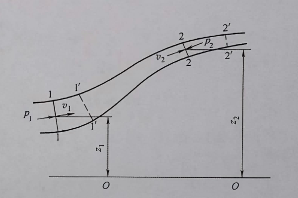
Figure 1-14: Schematic for derivation of Bernoulli's equation
The work done by the resultant force F₂ at cross-section 2-2 on the fluid during time dt is:
W₂ = F₂ds₂ = -p₂A₂v₂dt
Therefore, the total work done by external forces on the fluid segment 1-2 during time dt is:
W = W₁ + W₂ = p₁A₁v₁dt - p₂A₂v₂dt
Introducing the condition that the fluid is incompressible, from the equation A₁v₁ = A₂v₂ = constant, we have:
A₁v₁ = A₂v₂ = Q
Substituting this into the work equation gives:
W = (p₁ - p₂)Qdt
Complete Bernoulli Equation
Extending this derivation to include gravitational potential energy and kinetic energy changes, the complete Bernoulli equation for ideal fluids is:
z₁ + p₁/γ + v₁²/(2g) = z₂ + p₂/γ + v₂²/(2g) = constant
Where:
- z = elevation head (potential energy per unit weight)
- p/γ = pressure head (pressure energy per unit weight)
- v²/(2g) = velocity head (kinetic energy per unit weight)
- γ = specific weight of the fluid
- g = acceleration due to gravity
Venturi Effect
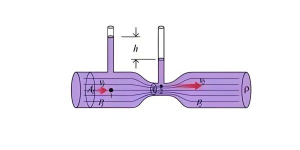
The Venturi effect demonstrates how fluid pressure decreases as velocity increases in a constricted section of a pipe, directly illustrating Bernoulli's principle. This effect is widely used in flow measurement devices and injection systems.
Understanding this phenomenon is key to answering how do hydraulics work in applications ranging from carburetors to industrial flow meters, where pressure differences created by velocity changes drive fluid behavior.
Hydraulic Machinery
Bernoulli's equation is fundamental to the operation of hydraulic machinery like pumps and turbines, which convert between mechanical and fluid energy. These devices rely on controlled changes in fluid pressure and velocity to perform work.
Engineers apply Bernoulli's principles to optimize the design of such machinery, ensuring efficient energy conversion and answering the practical question of how do hydraulics work in power generation and fluid transport systems.
Practical Significance of Bernoulli's Equation
Bernoulli's equation is a cornerstone of fluid mechanics with profound practical implications. It explains how fluid energy transforms between different forms (potential, pressure, and kinetic) as the fluid moves through a system, which is essential to understanding how do hydraulics work in countless engineering applications.
From the simplest water faucet to complex hydraulic systems in heavy machinery, Bernoulli's principles govern fluid behavior. By applying this equation, engineers can predict pressure changes, design efficient flow systems, and solve practical problems related to fluid transport and energy conversion.
When combined with the continuity equation, Bernoulli's equation provides a powerful framework for analyzing fluid systems, enabling engineers to answer how do hydraulics work in both theoretical and practical contexts.
Understanding Fluid Dynamics
The principles of fluid dynamics—including the basic concepts of fluid motion, the continuity equation, and Bernoulli's equation—provide the foundation for explaining how fluids behave under various conditions. These principles collectively answer the fundamental question of how do hydraulics work in natural phenomena and engineered systems alike.
From the flow of water in pipes to the aerodynamics of aircraft, fluid dynamics plays a crucial role in countless aspects of our world. A thorough understanding of these principles enables engineers and scientists to design more efficient systems, predict fluid behavior, and solve complex practical problems.
Learn more