Fundamentals of Fluid and Hydraulics
A comprehensive guide to hydraulic fluid mechanics, covering viscosity, kinematics, statics, dynamics, pipe flow, and orifice flow.
1. Hydraulic Fluid Viscosity and Specific Heat
Viscosity is a fundamental property of hydraulic fluids that measures their resistance to flow. In fluid and hydraulics systems, understanding viscosity is critical for designing efficient components and predicting performance.
Newtonian vs. Non-Newtonian Fluids
Newtonian fluids, such as mineral oils, exhibit a linear relationship between shear stress and shear rate. Non-Newtonian fluids, like some synthetic lubricants, have a nonlinear relationship.
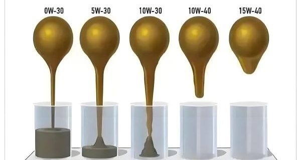
The viscosity of a fluid and hydraulics system is influenced by temperature and pressure. As temperature increases, viscosity typically decreases, while pressure increases generally lead to higher viscosity.
Viscosity Index (VI)
The viscosity index is a measure of how much a fluid's viscosity changes with temperature. A higher VI indicates less viscosity change:
| Fluid Type | Viscosity Index (VI) |
|---|---|
| Mineral Oil | 90-100 |
| High VI Mineral Oil | 100-120 |
| Synthetic Oil | 130-170 |
Specific heat is another critical property in fluid and hydraulics systems. It is the amount of heat required to raise the temperature of a unit mass of fluid by one degree. In hydraulic systems, fluids with high specific heat are preferred as they can absorb more heat without significant temperature rise.
Key Formulas
Dynamic Viscosity (μ): τ = μ * (du/dy)
Kinematic Viscosity (ν): ν = μ/ρ
Specific Heat (c): Q = mcΔT
Practical Application
In hydraulic systems, maintaining proper viscosity is essential. Too high viscosity increases energy consumption, while too low viscosity can cause wear due to insufficient lubrication. For example, in cold environments, a fluid with a high VI or a synthetic fluid might be selected to ensure adequate viscosity.
Section Contents
- Viscosity Definition
- Temperature & Pressure Effects
- Viscosity Measurement
- Specific Heat Capacity
- Applications in Fluid & Hydraulics
Related Resources
Quick Reference
Dynamic Viscosity Units:
- • Pascal-second (Pa·s)
- • Poise (P)
- • Centipoise (cP)
Kinematic Viscosity Units:
- • Square meter per second (m²/s)
- • Stokes (St)
- • Centistokes (cSt)
2. Fluid Kinematics Fundamentals
hydraulic scientific principles:Fluid kinematics is the study of fluid motion without considering the forces that cause the motion. In fluid and hydraulics, this involves analyzing velocity, acceleration, and flow patterns of fluids.
Lagrangian vs. Eulerian Approach
In the Lagrangian approach, we track individual fluid particles. In the Eulerian approach, we analyze the flow at fixed points in space.
Types of Fluid Flow
- Steady vs. Unsteady Flow: Flow parameters do not change with time in steady flow.
- Uniform vs. Non-Uniform Flow: Flow parameters do not change with position in uniform flow.
- Laminar vs. Turbulent Flow: Laminar flow is smooth, while turbulent flow is chaotic.
Velocity and Acceleration Fields
In fluid and hydraulics, the velocity field is a vector field that describes the velocity of a fluid at every point in space and time:
V(x, y, z, t) = u(x, y, z, t)i + v(x, y, z, t)j + w(x, y, z, t)k
The acceleration of a fluid particle is given by:
a = ∂V/∂t + (V·∇)V
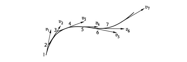
Streamlines, Pathlines, and Streaklines
These are important concepts for visualizing fluid flow:
Streamlines
Tangent to the velocity vector at every point. Instantaneous flow direction.
Pathlines
Path followed by individual fluid particles over time.
Streaklines
Locus of all particles that have passed through a fixed point.
Continuity Equation
The continuity equation is a statement of conservation of mass for fluid flow. For incompressible fluids, it simplifies to:
∇·V = 0
or in Cartesian coordinates:
∂u/∂x + ∂v/∂y + ∂w/∂z = 0
For a control volume:
∂ρ/∂t + ∇·(ρV) = 0
where ρ is density, V is velocity vector.
Practical Application
In hydraulic systems, understanding fluid kinematics helps in designing efficient pipelines and components. For example, analyzing flow patterns around valves and pumps ensures minimal energy losses and prevents cavitation.
3. Fluid Statics
Fluid statics deals with fluids at rest and the hydraulic pressure distribution within the fluid. In fluid and hydraulics, this is crucial for understanding forces on submerged surfaces and in hydraulic systems.
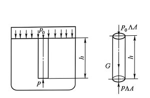
Hydrostatic Pressure
The pressure in a fluid at rest increases with depth due to the weight of the fluid above. The hydrostatic pressure is given by:
p = p₀ + ρgh
where p₀ is the pressure at the surface, ρ is fluid density, g is acceleration due to gravity, and h is depth.
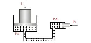
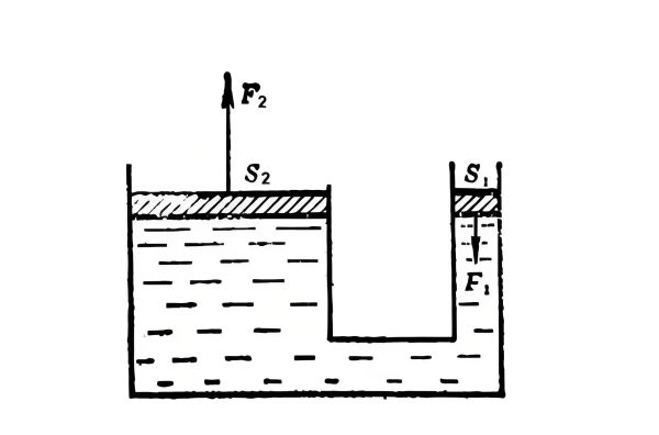
Pascal's Law
Pressure applied to an enclosed fluid is transmitted undiminished to every portion of the fluid and the walls of the containing vessel.
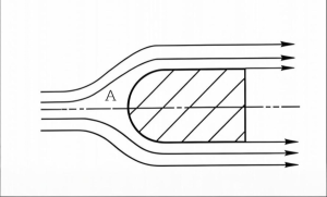
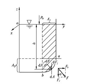
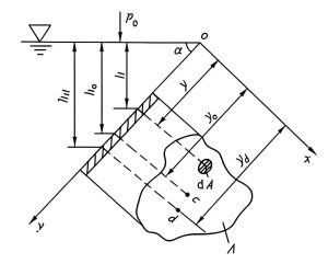
Forces on Submerged Surfaces
In fluid and hydraulics, calculating forces on submerged surfaces is important for designing dams, gates, and other structures. The resultant hydrostatic force on a plane surface is:
F = ρgȳA
where ȳ is the distance from the fluid surface to the centroid of the area A.
Horizontal Surface
The force is uniform and acts at the centroid of the surface.
Vertical Surface
The force increases with depth and acts below the centroid.
Buoyancy and Archimedes' Principle
Archimedes' principle states that the buoyant force acting on a body immersed in a fluid is equal to the weight of the fluid displaced by the body:
F_buoyancy = ρgV
where V is the volume of fluid displaced.
Stability of Floating Bodies
For a floating body to be stable, the metacenter (M) must be above the center of gravity (G):
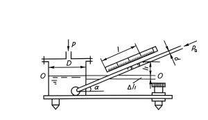
Manometry
Manometers are devices used to measure pressure in fluid and hydraulics systems. Common types include:
U-Tube Manometer
Measures pressure difference using a U-shaped tube filled with a liquid.
Inclined Manometer
Increases sensitivity by using an inclined tube.
Differential Manometer
Measures the difference between two pressures.
Practical Application
In hydraulic lifts and presses, Pascal's law is used to multiply force. A small force applied to a small piston creates a pressure that is transmitted to a larger piston, resulting in a larger force. This principle is fundamental in fluid and hydraulics applications.
4. Fluid Dynamics
How do hydraulics work. Fluid dynamics studies the behavior of fluids in motion and the forces acting on them. In fluid and hydraulics, this is essential for analyzing pumps, turbines, and flow in pipes.
Bernoulli's Equation
For steady, incompressible, inviscid flow along a streamline, Bernoulli's equation states:
p + ½ρv² + ρgh = constant
where p is pressure, ρ is density, v is velocity, g is gravity, and h is height.
Navier-Stokes Equations
The Navier-Stokes equations describe the motion of viscous fluid substances and are fundamental in fluid and hydraulics:
ρ(∂v/∂t + v·∇v) = -∇p + μ∇²v + ρg
where μ is dynamic viscosity.
Momentum Equation
The momentum equation is a statement of Newton's second law and is crucial for analyzing forces in fluid and hydraulics systems:
ΣF = ∂/∂t ∫_CV ρv dV + ∫_CS ρv(v·n) dA
For steady flow with one inlet and one outlet:
F = ρQ(V_out - V_in)
Dimensional Analysis and Similarity
In fluid and hydraulics, dimensional analysis helps in reducing the number of variables and ensuring similarity between model and prototype:
Reynolds Number (Re)
Ratio of inertial forces to viscous forces:
Re = ρvL/μ
Froude Number (Fr)
Ratio of inertial forces to gravitational forces:
Fr = v/√(gL)
Mach Number (Ma)
Ratio of flow velocity to the speed of sound:
Ma = v/c
Flow Measurement
Common methods for measuring flow rate in fluid and hydraulics systems include:
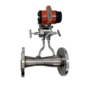
Venturi Meter
Uses pressure difference across a constriction:
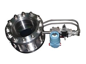
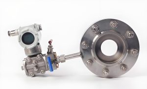
Orifice Plate
Measures flow by creating a pressure drop:
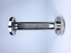
Rotameter
Variable area flow meter with a float:
Practical Application
In fluid and hydraulics systems, pumps and turbines are designed using principles of fluid dynamics. For example, centrifugal pumps use rotational energy from an impeller to increase the pressure and flow rate of a fluid.
5. Fluid Flow in Pipelines
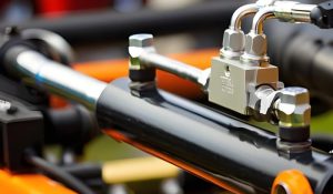
Hydraulic Flow Control valveUnderstanding fluid flow in pipelines is critical in fluid and hydraulics for designing efficient distribution systems and minimizing energy losses.
Laminar vs. Turbulent Flow
The flow regime in pipes depends on the Reynolds number:
- • Laminar flow: Re < 2000
- • Transitional flow: 2000 < Re < 4000
- • Turbulent flow: Re > 4000
Head Loss in Pipes
Head loss in pipes is due to friction and minor losses from fittings:
h_L = f (L/D) (v²/2g)
where f is the friction factor, L is pipe length, D is diameter, v is velocity, and g is gravity.
Friction Factor Calculation
The friction factor depends on the flow regime and pipe roughness:
Laminar Flow
For laminar flow, the friction factor is:
f = 64/Re
Turbulent Flow
For turbulent flow, use the Colebrook equation:
1/√f = -2 log₁₀[(ε/D)/3.7 + 2.51/(Re√f)]
where ε is pipe roughness.
Moody Chart for Friction Factor Determination
Minor Losses
Minor losses occur due to fittings, valves, bends, and contractions/expansions:
h_L = K (v²/2g)
where K is the loss coefficient specific to the fitting.
| Fitting | Loss Coefficient (K) |
|---|---|
| Globe Valve (fully open) | 10.0 |
| Gate Valve (fully open) | 0.19 |
| 90° Elbow (standard) | 0.9 |
| Sudden Expansion | (1 - A₁/A₂)² |
Pump Power Requirements
In fluid and hydraulics systems, pumps are used to overcome head losses and provide the required flow rate. The power required is:
P = ρgQH/η
where Q is flow rate, H is total head, and η is pump efficiency.
Net Positive Suction Head (NPSH)
To prevent cavitation, the available NPSH must be greater than the required NPSH:
NPSH = (p₁/ρg) + (v₁²/2g) - p_v/ρg
where p_v is the vapor pressure of the fluid.
Practical Application
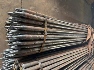
In industrial fluid and hydraulics systems, proper pipe sizing and material selection are crucial to minimize energy losses. For example, using smooth pipes and minimizing the number of fittings can reduce head losses and lower pumping costs.
6. Orifice Flow and Gap Flow
Hydraulic Flow Meter: Orifice and gap flows are common in fluid and hydraulics systems, used for flow control, measurement, and leakage analysis.
Orifice Flow
Flow through an orifice is governed by:
Q = C_d A √(2Δp/ρ)
where C_d is the discharge coefficient, A is orifice area, and Δp is pressure difference.
Discharge Coefficient
The discharge coefficient accounts for non-ideal flow effects:
- • For sharp-edged orifices: C_d ≈ 0.61
- • For rounded orifices: C_d ≈ 0.97
- • Depends on Reynolds number and orifice geometry
Types of Orifices
Orifices are classified based on their shape and edge characteristics:
Sharp-Edged Orifice
Has a sharp edge to minimize contact with the fluid:
Round-Edged Orifice
Smoother entry reduces turbulence:
Bevelled Orifice
Used to control the direction of flow:
Flow Through Gaps
Flow through gaps (such as between pistons and cylinders) is important for leakage analysis in fluid and hydraulics systems:
Parallel Plate Gap
Flow rate for laminar flow between parallel plates:
Q = (bh³Δp)/(12μL)
where b is width, h is gap height, L is length.