Hydraulic Symbols Identification
A comprehensive guide to understanding and interpreting hydraulic symbols in fluid power systems, covering valves, pumps, motors, cylinders, and auxiliary components.
1. Identification of Hydraulic Valves
Hydraulic valves are essential components in fluid power systems, controlling the pressure, flow rate, and direction of hydraulic fluid. Understanding hydraulic symbols for various valve types is fundamental to reading and interpreting hydraulic schematics accurately. Each valve type has a specific representation in hydraulic symbols that conveys its function, operation, and characteristics.
1.1 Directional Control Valves
Directional control valves manage the path of hydraulic fluid within a system. The basic hydraulic symbols for these valves consist of square or rectangular envelopes representing valve positions, with lines indicating flow paths.
- 2-way valves: Represented by a single square with two connection ports
- 3-way valves: Feature three connection ports in their symbolic representation
- 4-way valves: Most common type, shown with four connection ports
- Check valves: Display a spring and ball/plunger to indicate one-way flow
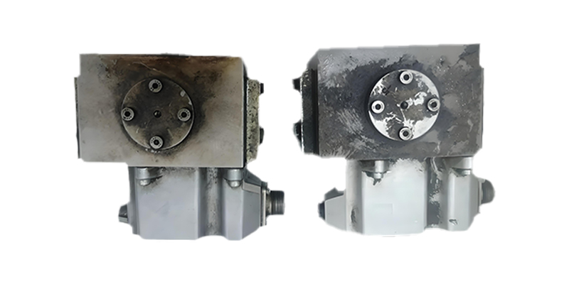
1.2 Pressure Control Valves
These valves regulate system pressure and protect components from overpressure. Their hydraulic symbols typically include a spring element to indicate pressure setting capability.
- Relief valves: Symbol includes a spring and adjustable knob
- Pressure reducing valves: Feature a directional arrow indicating pressure reduction
- Sequence valves: Combine elements of relief and check valves in their symbol
- Unloading valves: Show a pilot line connection in their symbolic representation
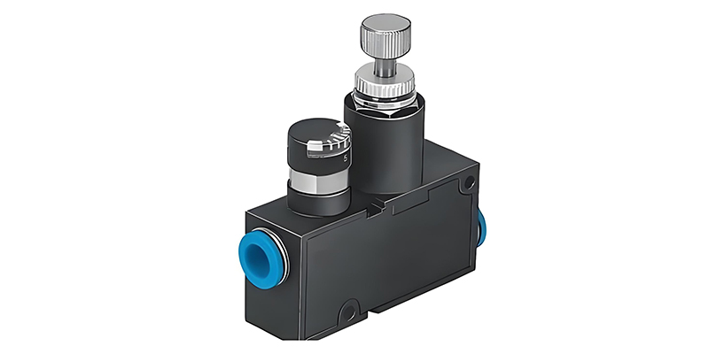
1.3 Flow Control Valves
Flow control valves regulate the rate of fluid flow in hydraulic circuits. Their hydraulic symbols often incorporate a restriction element and may include check valve features for bypass capability.
- Fixed flow controls: Represented by a simple restriction symbol
- Adjustable flow controls: Include an arrow or adjustment mechanism in their symbol
- Pressure-compensated flow controls: Add a spring element to indicate compensation
- Needle valves: Show a pointed adjustment mechanism in their symbolic representation
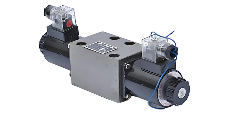
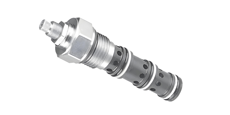
1.4 Proportional and Servo Valves
These precision valves provide variable control proportional to an input signal. Their hydraulic symbols include electrical connection indicators and often show more detailed internal flow paths.
- Proportional valves: Symbol includes a coil or electrical connection
- Servo valves: Feature feedback lines in their symbolic representation
- Electro-hydraulic valves: Combine electrical and hydraulic elements in their symbols
- Cartridge valves: Show a simplified body with insert representation
Key Principles for Valve Identification
When interpreting hydraulic symbols for valves, remember these fundamental principles: Valves are represented by one or more squares (envelopes) indicating their positions. Ports are shown as lines entering or exiting these squares. Actuation methods (manual, hydraulic, electrical) are indicated by symbols attached to the envelope. Spring returns are shown as spring symbols. Understanding these basic elements will significantly improve your ability to recognize and interpret any valve symbol in hydraulic schematics.
2. Identification of Hydraulic Pumps, Motors and Cylinders Symbols
The primary actuators and energy converters in hydraulic systems are pumps, motors, and cylinders. When designing hydraulic system schematics—where clarity and quick interpretation are critical—their hydraulic symbols take the form of hydraulic schematic symbols (symbols optimized to show not just device characteristics, but also potential connections and control logic in a schematic layout). These hydraulic symbols are distinctive and relatively easy to recognize once you understand their basic components, and as hydraulic schematic symbols, they further convey essential information about the device's operation, type, and characteristics without requiring detailed engineering drawings.
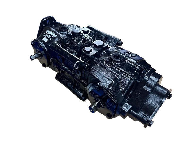
2.1 Hydraulic Pumps
Hydraulic pumps convert mechanical energy into hydraulic energy. Their hydraulic symbols typically feature a circle with internal arrows indicating fluid flow direction and additional symbols denoting specific pump types.
Gear Pumps
Represented by two interlocking gear symbols within the circular envelope. Fixed displacement gear pumps show simple gear symbols, while variable displacement models add adjustment mechanisms.
Vane Pumps
Feature a rotor with vanes in their symbolic representation. The basic circle includes a slotted rotor and vanes, with variable displacement versions showing an adjustment arrow or mechanism.
Piston Pumps
Display a piston arrangement within the circle. Axial piston pumps show pistons parallel to the centerline, while radial piston pumps show pistons arranged radially. Variable displacement models include a swash plate or angle adjustment symbol.
Pump Characteristics in Symbols
Fixed displacement pumps have simple, unadjustable symbols, while variable displacement pumps include arrows or adjustment mechanisms. Pressure-compensated pumps add a spring or pressure feedback line to their hydraulic symbols.
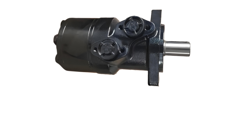
2.2 Hydraulic Motors
Hydraulic motors convert hydraulic energy back into mechanical energy. Their hydraulic symbols are similar to pump symbols but with reversed flow arrows indicating energy conversion direction.
- Gear motors: Similar to gear pumps but with reversed arrows
- Vane motors: Feature rotor and vanes with appropriate flow direction
- Piston motors: Show piston arrangement with reversed energy flow
- Fixed vs. variable displacement: Indicated similarly to pumps with adjustment features
- Rotation direction: Often indicated by arrows in the motor symbol
A key distinction in hydraulic symbols between pumps and motors is the direction of arrows, indicating the direction of fluid flow relative to the device.
2.3 Hydraulic Cylinders
Hydraulic cylinders convert fluid energy into linear mechanical force and motion. Their hydraulic symbols are more linear in design compared to pumps and motors, representing the cylinder barrel and piston arrangement.
- Single-acting cylinders: Show one port with a spring return mechanism
- Double-acting cylinders: Feature two ports for bidirectional operation
- Telescoping cylinders: Display multiple nested sections in their symbol
- Cushioned cylinders: Include dash symbols at one or both ends
- Rodless cylinders: Feature a different symbolic representation for the piston
The hydraulic symbols for cylinders clearly indicate their stroke direction, mounting style, and any special features like cushions or position sensors.
Comparative Analysis of Energy Converters in Hydraulic Symbols
| Component | Basic Symbol Shape | Key Identifiers | Energy Conversion |
|---|---|---|---|
| Hydraulic Pump | Circle | Internal elements (gears, vanes, pistons) with arrows pointing out | Mechanical → Hydraulic |
| Hydraulic Motor | Circle | Similar internal elements with arrows pointing in | Hydraulic → Mechanical |
| Hydraulic Cylinder | Rectangle with piston rod | Piston representation with ports and end features | Hydraulic → Linear Mechanical |
3. Identification of Hydraulic Auxiliary Components Symbols
While pumps, motors, cylinders, and valves are the primary components in hydraulic systems, auxiliary components are essential for proper system operation, maintenance, and safety. These components include reservoirs, filters, accumulators, heat exchangers, and various connectors. hydraulic circuit symbols—which incorporate their hydraulic symbols alongside those of primary components—are equally important for understanding complete system schematics. Recognizing these hydraulic symbols within hydraulic circuit symbols ensures you can interpret the entire hydraulic system, not just its primary functional components, as the circuit symbols reveal how auxiliary components interact with primary ones in the full system.
3.1 Reservoirs and Tanks
Reservoirs store hydraulic fluid and help with cooling and air separation. Their hydraulic symbols are typically rectangular with additional symbols indicating features.
- Basic open reservoir: Simple rectangle
- Pressurized reservoir: Rectangle with pressure indicator
- Baffled reservoir: Rectangle with internal divider line
- With return line: Inlet symbol with optional diffuser
- With suction line: Outlet symbol with strainer representation
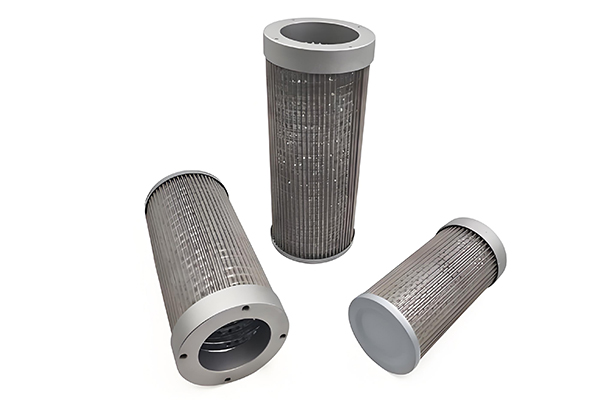
3.2 Filters and Strainers
These components remove contaminants from hydraulic fluid. Their hydraulic symbols feature a grid or mesh pattern indicating the filtering element.
- Suction strainer: Mesh symbol in inlet line
- Return line filter: Mesh with directional flow arrow
- Pressure line filter: Heavy-duty symbol with reinforcement
- Filter with bypass: Mesh with parallel check valve
- Indicating filter: Basic filter with indicator symbol
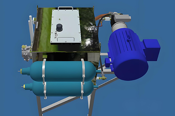
3.3 Accumulators
Accumulators store hydraulic energy for later use. Their hydraulic symbols vary by type but generally include a pressure vessel representation.
- Bladder accumulator: Ellipse with internal divider
- Piston accumulator: Cylinder with piston symbol
- Diaphragm accumulator: Oval with flexible divider
- Spring-loaded accumulator: Cylinder with spring
- Gas-charged accumulator: Includes gas precharge symbol
3.4 Heat Exchangers
These components regulate fluid temperature in hydraulic systems. Their hydraulic symbols incorporate cooling or heating elements.
- Oil cooler: Series of parallel lines with cooling symbol
- Water-cooled exchanger: Includes water line connections
- Air-cooled exchanger: Features fin symbols for heat dissipation
- Heater: Similar to cooler but with heating element symbol
- Thermostatic: Includes temperature-sensitive element
3.5 Connectors and Fittings
These components join system elements. Their hydraulic symbols are relatively simple but important for understanding system layout.
- Straight connector: Simple line connection
- Elbow fitting: 90-degree angle in line
- Tee fitting: Three-way connection symbol
- Union: Line with small perpendicular mark
- Quick disconnect: Special coupling symbol
3.6 Measurement and Control
Gauges, sensors, and other devices monitor system parameters. Their hydraulic symbols clearly indicate their measurement function.
- Pressure gauge: Circle with "P" inside
- Flow meter: Circle with "Q" and arrow
- Temperature gauge: Circle with "T" inside
- Level indicator: Rectangle with sight glass symbol
- Pressure switch: Pressure symbol with electrical contacts
Auxiliary Component Symbols in System Context
Understanding how auxiliary components integrate into complete hydraulic systems is crucial for proper schematic interpretation. These components may not be the primary work-producing elements, but their hydraulic symbols provide essential information about system safety, maintenance, and operation.
For example, the presence of a filter symbol in the return line indicates where fluid cleanliness is maintained, while an accumulator symbol shows energy storage capability. Recognizing these hydraulic symbols helps identify potential maintenance points, safety features, and system capabilities that might not be apparent from primary components alone.
When analyzing complete schematics, pay attention to how auxiliary components interact with primary components. A pressure gauge symbol near a relief valve provides insight into system pressure monitoring points, while a cooler symbol indicates thermal management considerations. Together, all these hydraulic symbols create a complete picture of the hydraulic system's design and functionality.
Mastering Hydraulic Symbols
The ability to recognize and interpret hydraulic symbols is fundamental to working with fluid power systems. From valves that control flow direction and pressure to pumps that generate hydraulic power, and from cylinders that produce linear motion to the auxiliary components that support system operation, each symbol conveys essential information in a standardized format.
By understanding the principles behind hydraulic symbols and recognizing the key features of each component's representation, you can effectively read, design, maintain, and troubleshoot hydraulic systems. Regular practice with schematics will reinforce your knowledge and make symbol recognition second nature, enabling you to work more efficiently and accurately with hydraulic systems.